
A mini measurement project exploring op-amp behaviour, virtual grounds, and practical audio signal conditioning.
Motivation
I wanted to refresh and deepen my understanding of op-amps—both the basic theory and the practical considerations that matter in real circuits. Having been a while since I studied op amps formally, I put together a few circuits to review their use in some common applications: how inverting and non-inverting topologies behave, how biasing works in single-supply systems, and how to characterize real-world performance beyond the textbook formulas.
I had some TL071 JFET op-amps on hand, so I designed and built two small audio-frequency amplifiers—a non-inverting stage and an inverting stage—using TL071 JFET op-amps powered from a single 9 V supply with a virtual ground. I then performed a set of measurements (gain, frequency response, output swing limits, load driving capability, etc.) to compare theory with practice.
This resulted in a compact but realistic audio test amplifier, and a complete characterization write-up I can reference in future projects involving op-amps.
Implementation
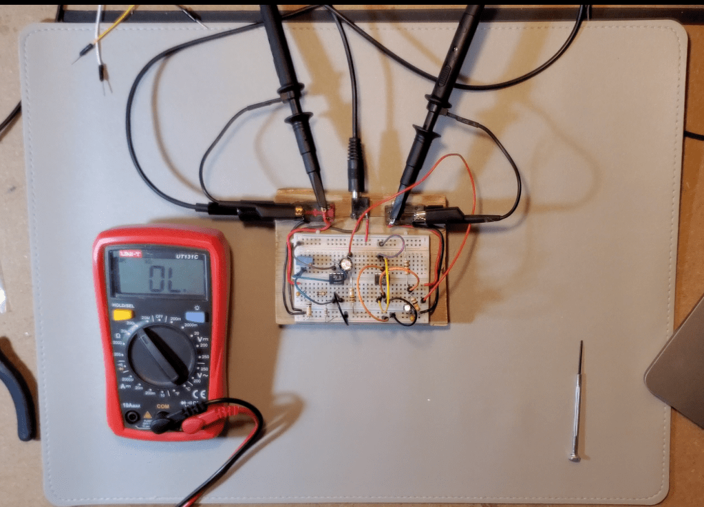
Hardware Overview
- Op amp: TL071 (2 units used)
- Supply: Single 9 V battery
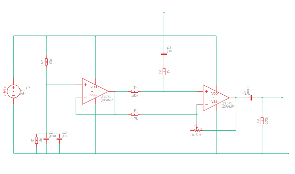
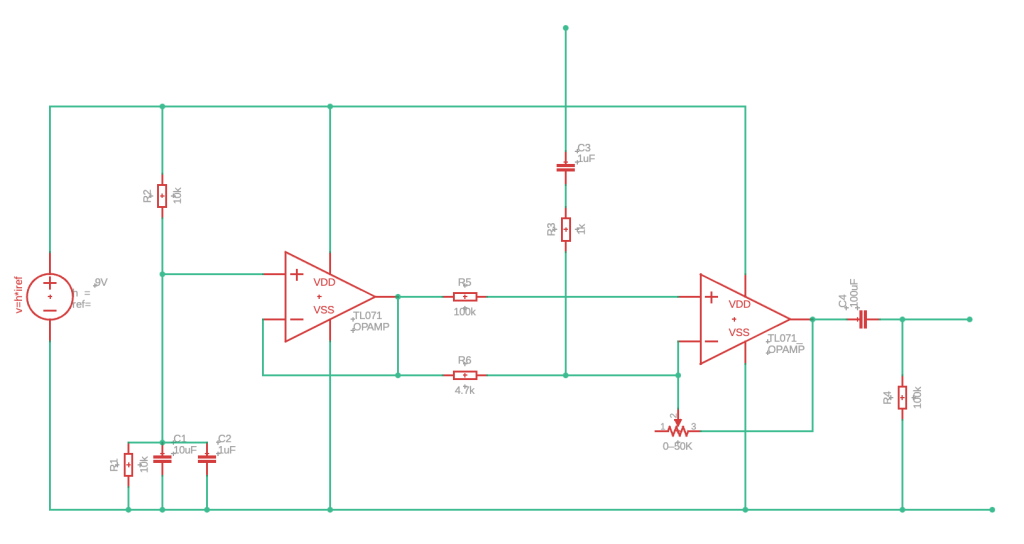
- Virtual ground: Resistive divider (10 kΩ / 10 kΩ) buffered by a TL071 configured as a voltage follower, producing Vref ≈ 4.5 V
- Topologies built:
- Non-inverting amplifier (adjustable gain, AC-coupled input and output)
- Inverting amplifier (fixed–gain configuration)
- Input source: Laptop headphone output (≈2.9 Vpp max)
- Measurement equipment: Digital oscilloscope + multimeter
Biasing and Single-Supply Considerations
Because the TL071 is not rail-to-rail, it cannot accept or produce signals referenced directly to 0 V when powered from a single 9 V supply. All audio signals were therefore AC-coupled and biased around Vref ≈ 4.5 V, giving the op amp a usable ±4.5 V internal swing.
Each TL071 had a 1 µF ceramic decoupling capacitor directly across its supply pins (pin 7 ↔ pin 4), and the virtual ground node used a larger electrolytic (10 µF) for stability. These are essential to prevent oscillation and settling transients.
Measurement Challenges and Solutions
When attempting to probe the input node after the coupling capacitor, the circuit became unstable. This was traced to the fact that the scope ground clip is at 0 V, but the input node is biased at Vref. Direct probing partially shorted the biasing network. To avoid this and similar issues, I was sure to:
- Always measure Vin before the coupling cap (0 V-referenced)
- Measure Vout at the internal op-amp output (Vref-centered)
- Use Vpp ratios for gain measurements
- Treat scope ground only as real ground, never as Vref
Results & Findings
DC Operating Point
| Node | Measured Voltage (V) |
| Power Supply | 9.41 |
| Virtual Ground | 4.69 |
| Non-Inverting Input (Amp) | 4.64 |
| Inverting Input (Amp) | 4.69 |
| Output (Pre-Output Cap) | 4.70 |
| Output (Post-Cap) | 0.00 |
- Vref stabilized at approximately half the supply (4.69 V).
- Both op-amp inputs tracked within a few mV of Vref.
- Internal output nodes (pre–coupling cap) also sat at Vref, as expected for AC-coupled designs.
Takeaway: The virtual ground behaved as intended, and biasing was correct for both topologies.
Closed-Loop Gain vs Theory
Non-Inverting Configuration (1 kHz)
| Rf (kΩ) | Rg (kΩ) | Av (theory) | Vin_pp | Vout_pp | Av (measured) | Error (%) |
| 50.60 | 4.63 | 11.93 | 0.48 | 5.72 | 11.91 | 0.1 |
- Rf = 50.6 kΩ, Rg = 4.63 kΩ → Avtheory = 1 + Rf/Rg = 11.93
- Measured using Vpp ratios → Avmeasured = 11.91 (0.1% error, well within expected tolerance)
Inverting Configuration (1 kHz)
| Rf (kΩ) | Rg (kΩ) | Av (theory) | Vin_pp | Vout_pp | Av (measured) | Error (%) |
| 10.20 | 1.00 | 10.20 | 0.42 | 4.20 | 10.00 | 2 |
- Rf = 10.20 kΩ, Rg = 1.00 kΩ → Avtheory = –Rf/Rg = 10.20
- Measured using Vpp ratios → Avmeasured = 10.00 (2 % error, higher than the non-inverting case, but still within expected tolerance)
Takeaway: Textbook gain formulas hold when biasing and loading are correct.
Frequency Response
Both amplifiers were tested from 5 Hz to ~10 kHz. Results (non-inverting case):
- Gain was surprisingly flat across the entire audio band (20 Hz–20 kHz).
- A 2.18 dB reduction in gain was measured at 5 Hz, consistent with the TL071’s gain-bandwidth product.
Inverting Case:
- Much more pronounced gain reduction at low frequencies, with a 3 dB point at 160 Hz.
- Noticeable phase shift at this point as well (0.27π radians).
- Effects due to the impedance of by the AC coupling capacitor.
- Theoretical values for this high-pass filter are given by
- ∠H=tan−1(ωRC) = 0.25π rad
Takeaway: TL071 offers ample bandwidth for audio signals, with high pass filtering characteristics closely matching the theoretical values.
Output Swing & Clipping Behaviour
With internal nodes centred around Vref, the TL071 produced:
- ~6.3 Vpp clean output (non-inverting) before clipping on a 9 V supply (increases to ~6.4 Vpp on inverting configuration)
- ~1.4 V of headroom required to each rail (consistent with datasheet)
Increasing input amplitude produced clean, predictable voltage clipping at the rails.
No instability or oscillations observed.
Takeaway: Real-world output limits match datasheet curves; single-supply headroom is limited but functional.
Load-Driving Capability
At one point, I tried connecting a small 8 ohm, 0.5 W speaker to both the input and the output of the amplifier. In the latter case, severe clipping of the output signal occurred. Further research revealed that this was due to current-limiting distortion caused by the large load.
According to the datasheet, the TL071 can only source/sink roughly 10 mA. Further load testing showed:
- High-impedance loads (≥10 kΩ, line-level input to external amplifier): Little to no change in output amplitude
- 1 kΩ load: Slight reduction in max clean swing
- 8 Ω speaker: Severe current-limit distortion, squared waveforms, and reduced amplitude
This behaviour is expected as op-amps are voltage devices, not power devices.
Takeaway: TL071 is suitable as a preamp/buffer but not a speaker driver.
Current limiting is safe but produces harsh distortion.
Phase Behaviour
- Non-inverting: Input and output in phase
- Inverting: Output shifted by ~180° (shift increases at low frequencies)
- Measurements matched the underlying topology behaviour perfectly
Takeaway: Confirms correct wiring and valid theoretical understanding.
Next Steps
This mini-project established a solid foundation for more advanced op-amp work. As the “lego-blocks” of analog circuit design, it’s about time that I reviewed their use and practical limitations.
My mind is already racing with possibilities for future projects.
Some examples:
- A headphone amplifier for my band’s rehearsal space
- Further exploration of controlled clipping in guitar fuzz, distortion, and overdrive circuits
- A general-purpose “tone-shaping” device for guitarists, employing adjustable filters in the op-amp’s feedback loop to selectively boost/cut certain frequencies
- An exploration of oscillation, using feedback to generate shapeable audio signals
Summary
This project demonstrated the end-to-end design and characterization of inverting and non-inverting op-amp amplifiers using a TL071 on a single supply. It covered:
- Virtual ground design
- Biasing considerations
- Measurement pitfalls
- Theoretical vs actual gain
- Bandwidth and slew behaviour (not discussed, but verified using square wave input)
- Load limitations and clipping behaviour
My goal was to go a little deeper than just replicating known circuits, and by building, measuring, and modifying the circuits described above, I’ve gone a long way toward building an intuition around op-amps and their applications, which will be invaluable in future work on audio devices.

Leave a comment